


 |
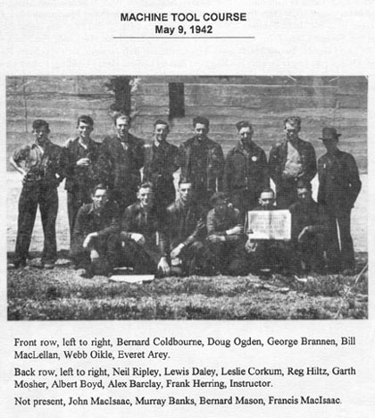
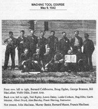
Machine Tool Course
|
An excerpt from Burt Baig’s letter: He recalls that the gun’s original design was by Vickers-Armstrong and brought over here from England and all the top technicians were British.
With the exception of the gun barrels which were made in Sorrel, Quebec, the entire gun was made in Trenton. Also that, as its various tests, it proved to be exceptionally accurate and was considered to be tops in its class by the military at that time. For sure the quality was recognized by the Navy according to many accounts.
George Scobie say that: The guns were produced in Trenton, a safe place, far from the war and bombs and already had the facilities close by, steel, shipping and not far from Halifax. He also believes that the “Frigates” were the lightest ships capable of using our guns although some destroyers might also have had them. He states that some guns were shipped to the Royal Indian Navy as he saw the destination on the crates before they were sealed over.
They were shown films at one time of our guns in action on a Canadian ship, but most information was secret so not much publicity was given out. He also recalls that the blueprints were British measure as opposed to American which would verify the guns were British.
Malcolm Sutherland in his 1986 letter states that he worked on almost every machine in the shop – including an “English lathe” where they turned the “rollers” that the guns turned on. His boss was Mr. Small (British). He states that the gun weighed 28 tons.
Fred Atwood says “I spent several years in The Canadian Armament Research And Development Establishment at Valcartier as a machinist and artificer. A twin mount 4 in. gun on loan from the Navy was used at CARDE for proof testing various component of the ammunition. I was not involved with any maintenance on the gun, but the Navy did not want it back when there was no further requirements for it, and CARDE was ordered to cut it up for scrap. I think the gun number was 08, I remember the men cutting up everything including the gear boxes, but I can’t remember if it was equipped with a medadyne unit.
Jim MacKenzie tells about some projects the men had to learn during their course as well as projects done in the lathes, drill press, shaper, and one on a miller. We did hand work with drills and files. The holes were drilling on the drill press and then were filed square for one project and triangular for another. The hole was 1 inch square in a 2 inch square piece Ľ” thick. Then we filed a 1 inch piece to go in the hole, by finger pressure in all 4 positions and not fall out when the outer piece was lifted. An almost impossible project for we novices. Even the instructor claimed a machinist could not do it. There was also a triangular hole and piece to go in it. Then one with 5 studs to put in 5 holes in another item and a plate with 5 holes only a 1/64” larger was supposed to go down on them 5 ways. That seemed the worst. We round filed the holes pretty big. The machine projects were not too bad. We threaded some pieces, not very difficult really, but was for us, who did not how to thread a shaft. Then there were neat fits and press fits. There were 22 projects in all.
|
Foremen
Lathes: Frank Campbell; Cecil Mercer; Alex Gordon; Don MacKenzie; Dan Chisholm
Grinders: Frank Lockwood; Mr. MacNaughton
Millers: Max Meadows
Paymaster: Tom Foster
Drills: Jimmie Dodge Fraser
Night Shift Superintendent: Tom Easton
Sub-Foreman: Everett MacKenzie
 |
Fig. 4- Finish turning flanged face of cast steel worm wheel box. Roughing cuts are taken in other less critical machines to extend the capacity of the Bullard.
The flanged face in Fig. 4 is being finished with a high speed tool cutting at approximately 40 ft. per min., with a feed of .018 in. and a depth cut about .005 in.
|
| Training and elevating of the 4 in. Twin Mark XIX is carried out with surprisingly small effort for a weapon of its size. This reflects the care and thought which has been given to the design as well as the degree of workmanship which is built into it. |
|
 |
Fig. 5 – shows the finish machining operations on the cradle casting of the mounting. The cradle casting of the mounting is a mild carbon steel casting, carbon being about .3%. It is the holder for the gun bodies and provides the necessary guides in which the guns may slide when they recoil. There are about 31 separate machining operations on this casting and the total machining time averages 395 hours per casting.
The operation shown is the finishing of the bronze bands which are expanded into grooves in the casting and which serve as sliding friction surfaces on which the guns slide when they recoil.
The boring of these bands must be done with extreme accuracy as the action of the mounting as a whole depends upon the relationship of one bore to the other. Tungsten carbide tools are used for the finishing operations on the bands. The machine shown in the photograph is a 5-in. Richards horizontal boring mill which is entirely suitable for this type of work.
|
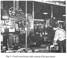
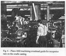
Fig. 6 - shows one of the earlier operations in the machining of a cradle casting. The particular detail shown is being carried out on a Cincinnati Plano-Miller. The operation is the milling of the outside face of the guide for the crosshead of the recuperator ram. A sheet metal cover bolts on to this face when assembled, to provide protection for the recuperator ram.
The machine shown is extremely useful for machining of odd surfaces such as that shown which are difficult to do with the usual run of machines.
|  |
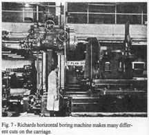 |
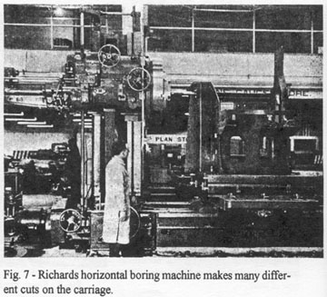
Fig. 7 – shows one of the boring operations on a carriage for the Mark XIX 4. in Twin.
The carriage is a fabricated steel plate assembly consisting of 5/8 in. nickel steel side plates which are offset and then reinforced around the edges with angle irons riveted in place. A sturdy cross-member is riveted between the two side plates to complete the assembly.
There are a number of holes which must be very accurately bored in the side places, and the 5 in. Richards horizontal boring mill shown in the photograph was well chosen for the work. The great flexibility of these machines makes them very useful for this kind of work.
We carry out seven different operations on the carriages on the horizontal boring mill which total up to 65 hours.
The fabricated steel carriage shown in Fig. 7 is bolted to the top racer plate and the remainder of the mounting is supported on the carriage. |
|
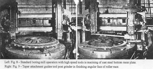
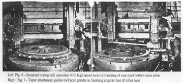
Fig. 8 – shows the rough machining operations on the bottom racer plate of the mounting. This is a mild steel casting and might well be termed the foundation of the mounting, as it is the part which bolts on to the desk of the ship. The machine shown is an 8-ft. vertical Cincinnati Hypro boring mill on which most of the main operations on these castings are carried out. The roughing cuts shown are being made with high speed steel tools at a speed of 48 ft. per min. Depth of cut is .2 in. and feed is .062 in. Time for the roughing cuts in 43 min. Finish turning operations are carried out with tungsten carbide tools operating at 203 ft. per min. Two finish cuts are taken, the first being .090 in. deep and the second .010 in. deep. Time for finishing turning is 46 min.
Fig. 9 – shows the grinding of the roller path on the top racer plate. This part operates in conjunction with the lower racer plate show in Fig. 8. The roller path of the lower racer plate is ground in the same manner as that shown Fig. 9. Stainless steel rollers, suitably tapered, and mounted on a retaining ring are assembled on the path of the lower racer plate. The top racer plate is then mounted on these rollers and revolves on them.
It is of the greatest importance that these main parts, such as racer plates, rollers and carriages, shall all be produced as accurately as possible to provide the final accuracy and ease of operation required in the complete assembly. The grinding of the roller paths is carried out with a work speed of 200 ft. per min. The wheel diameter is 6 in. and the specification of the wheel is 3860H8BE operating at 3,450 r.p.m. Time for grinding is 3 hours. Buffing of the roller path is also done with a work speed of 200 ft. per min. using a felt wheel 6 in. in diameter. No. 60 grit is glued on to this felt and the speed of the buffer is also 3,450 r.p.m. Time required to buff the path is 1ľ hours.
|
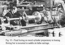 |
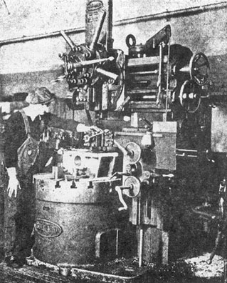
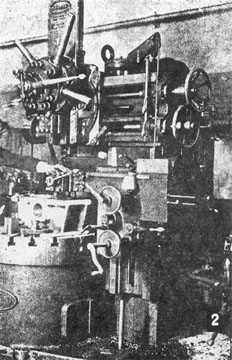
Fig. 10 – shows the final boring operation on a recoil cylinder is carried out on an American Pacemaker engine lathe using a high speed steel tool and a cast iron follower bushing. The recoil cylinder is a nickel steel forging, the nickel being about 2.25%, which produces a strong, tough material. The speed of the work is 23 ft. per min., the feed being .005 in. and the depth of cut being .025 in. After boring in this manner, the cylinders are honed to size, which produces a mirror finish in the bore.
|
|